Audio Processing (DSP)
Broadcast-grade signal processing chain with per-processor bypass, reordering, and presets.
DSP Chain Overview
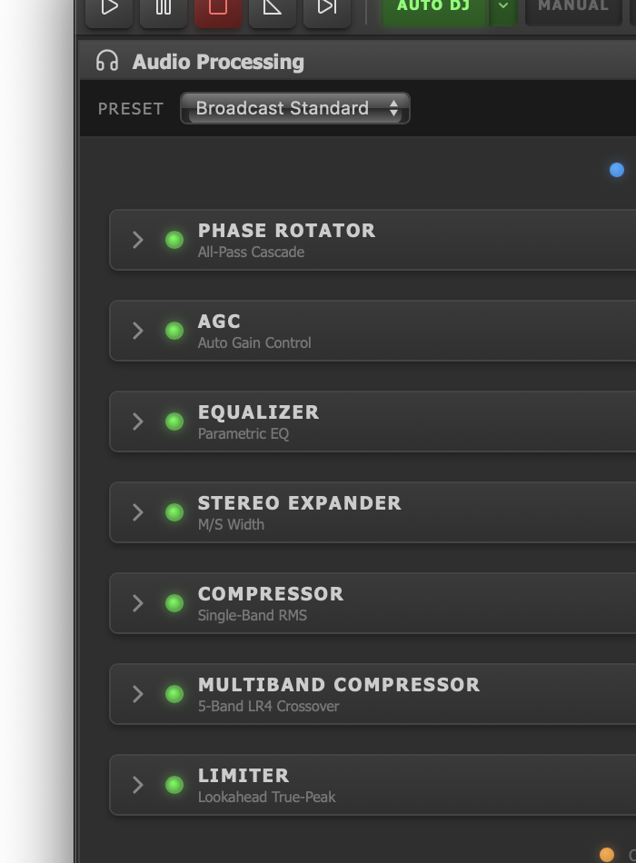
The DSP processor chain showing the sequential signal processing stages from Phase Rotator through Limiter.
The Audio Processing tab in JaiCast's main window exposes a modular DSP pipeline that sits between the mixer output and the encoder stage. Every audio sample passes through this chain before reaching your listeners. The chain processes audio sequentially from top to bottom, and you can reorder processors to shape the signal path to suit your format.
Each processor in the chain can be independently enabled or disabled without removing it, allowing instant A/B comparisons. All processors provide real-time IN/OUT metering so you can monitor the effect of each stage on the signal.
Default Chain Order
The default broadcast chain processes audio in the following order:
- Phase Rotator — reduce asymmetric peaks
- AGC — normalize long-term level
- 5-Band Parametric EQ — tonal shaping
- Stereo Expander — width and bass mono control
- Compressor — dynamic range reduction
- Multiband Compressor — per-band dynamics
- Limiter — final peak control and loudness metering
An optional FX Engine slot can be inserted anywhere in the chain for effects processing (reverb, delay, chorus, etc.).
Presets
JaiCast ships with four built-in chain presets that configure which processors are active and in what order:
| Preset | Chain | Use Case |
|---|---|---|
| Broadcast Standard | Phase Rot, AGC, EQ, Stereo, Comp, Multiband, Limiter | Full broadcast processing for FM/HD/streaming |
| Music | Phase Rot, AGC, EQ, Stereo, Multiband, Comp, Limiter | Music-forward with multiband before single-band comp |
| Voice | Phase Rot, AGC, Comp, EQ, Limiter | Spoken word, podcasts, talk format |
| Minimal | Phase Rot, Limiter | Transparent peak control with minimal coloration |
You can also save and load your own custom presets, preserving both the chain order and each processor's parameter values.
Phase Rotator
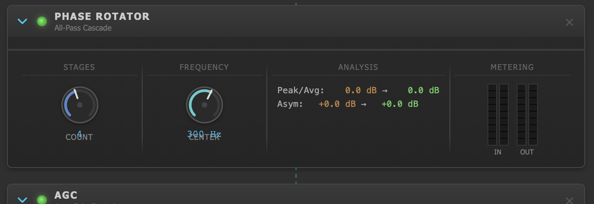
Phase Rotator with stages, frequency, and analysis display.
The Phase Rotator uses cascaded first-order all-pass filters to rotate the signal's phase without altering its frequency content. This reduces waveform asymmetry (the difference between positive and negative peaks), which in turn lowers the crest factor and allows downstream processors to work more efficiently with less gain reduction.
Controls
| Parameter | Range | Default | Description |
|---|---|---|---|
| Stages | 1 – 8 | 4 | Number of cascaded all-pass stages. More stages = stronger phase rotation. |
| Frequency | 50 – 1000 Hz | 300 Hz | Center frequency of the all-pass network. |
Analysis Display
The phase rotator provides a real-time analysis panel showing:
- Crest factor (dB) before and after rotation — lower values indicate more symmetrical peaks
- Asymmetry index (dB) before and after — measures the ratio of positive-to-negative peak excursion
- Waveform display — downsampled input vs. output waveform (~50ms window) for visual comparison
- IN/OUT metering — per-channel peak levels at the input and output of the processor
AGC (Automatic Gain Control)
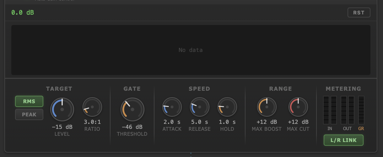
Automatic Gain Control with target, gate, speed, and range controls.
The AGC is a slow-acting leveler that normalizes the long-term loudness of incoming material. It compensates for level differences between tracks and sources before the signal reaches the compressor stages, ensuring a consistent input level for the rest of the chain.
Controls
| Parameter | Range | Default | Description |
|---|---|---|---|
| Target Level | dB | -15 dB | Desired output level. The AGC adjusts gain to drive the signal toward this target. |
| Detection Mode | RMS / Peak | RMS | Whether gain decisions are based on RMS (average power) or peak amplitude. |
| Ratio | — | 3.0 | Controls how aggressively the AGC corrects deviations from the target. |
| Gate Threshold | dB | -46 dB | Below this level, gain adjustment is frozen to prevent noise amplification during silence. |
| Attack | seconds | 2.0 s | Time to reduce gain when the signal exceeds the target. |
| Release | seconds | 5.0 s | Time to increase gain when the signal falls below the target. |
| Hold | seconds | 1.0 s | Time to hold gain steady once the signal is near the target, preventing hunting. |
| Max Boost | dB | 12 dB | Maximum gain increase allowed. |
| Max Cut | dB | 12 dB | Maximum gain reduction allowed. |
| L/R Link | On / Off | On | When enabled, gain adjustment is linked across both channels to preserve stereo imaging. |
Metering
The AGC panel displays:
- Current gain (dB) — the amount of boost or cut currently applied
- Gain history — a scrolling graph of gain adjustments over the last 15 seconds (20 Hz update rate)
- Input/Output peak levels — per-channel (L/R)
- Gate indicator — shows when the gate is active (signal below threshold)
5-Band Parametric Equalizer
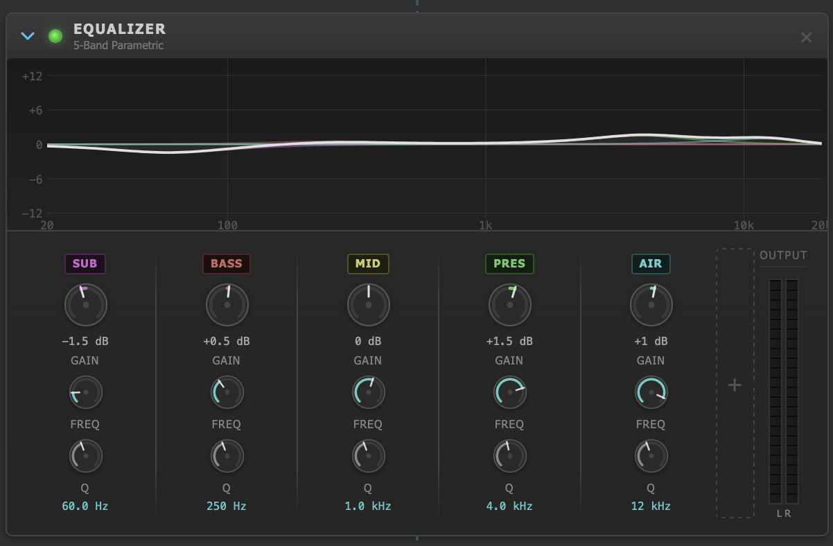
The 5-Band Parametric Equalizer with frequency response curve and color-coded band markers.
The parametric EQ provides five fully adjustable bands for tonal shaping. Each band is implemented as a biquad filter with double-precision (f64) coefficient computation for numerical stability. Bands are automatically labeled based on their center frequency.
Bands
| Band | Default Frequency | Typical Role |
|---|---|---|
| Sub | < 100 Hz | Sub-bass energy, rumble control |
| Bass | 100 – 400 Hz | Warmth, body, low-mid mud |
| Mid | 400 – 1500 Hz | Presence, vocal clarity |
| Pres (Presence) | 1.5 – 6 kHz | Detail, attack, intelligibility |
| Air | > 6 kHz | Sparkle, brilliance, high-frequency sheen |
Per-Band Controls
- Frequency (Hz) — center frequency of the band
- Gain (+/- dB) — boost or cut at the center frequency
- Q (bandwidth) — width of the filter bell; higher Q = narrower band
A visual frequency response curve renders in real time as you adjust parameters, overlaid with color-coded band markers. Output peak levels (L/R) are displayed below the curve.
Stereo Expander
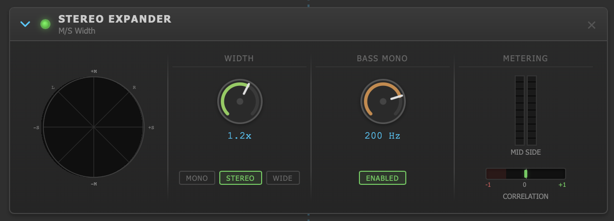
The Stereo Expander showing width control, bass mono crossover, and correlation metering.
The Stereo Expander operates in the Mid/Side domain to control the stereo width of the output signal. It also includes a bass mono crossover to collapse low-frequency content to mono, preventing phase-related issues with subwoofers and improving low-end coherence on streaming platforms.
Controls
| Parameter | Range | Default | Description |
|---|---|---|---|
| Width | 0.0 (Mono) – 2.0 (Wide) | 1.2 | Stereo width multiplier. 1.0 = unaltered, < 1.0 = narrower, > 1.0 = wider. |
| Bass Mono | On / Off | On | Enables the low-frequency mono crossover. |
| Bass Mono Freq | 20 – 400 Hz | 200 Hz | Frequencies below this value are collapsed to mono. Uses a Linkwitz-Riley 2nd-order crossover. |
Metering
- Mid level — peak amplitude of the center (mono-compatible) content
- Side level — peak amplitude of the difference (stereo-only) content
- Correlation meter — ranges from -1.0 (out of phase) through 0.0 (uncorrelated) to +1.0 (mono). Values below 0.0 indicate potential phase cancellation on mono playback systems.
- Output peak levels (L/R)
Compressor
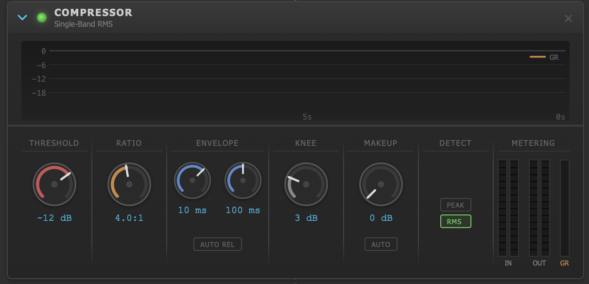
The single-band Compressor with threshold, ratio controls and scrolling gain reduction history.
The single-band compressor reduces the dynamic range of the overall signal. It supports both Peak and RMS detection modes, soft-knee compression, auto-release with dual-envelope tracking, and an optional sidechain highpass filter to prevent low-frequency content from driving excessive gain reduction.
Controls
| Parameter | Range | Default | Description |
|---|---|---|---|
| Threshold | -40 – 0 dB | -12 dB | Level above which compression begins. |
| Ratio | 1:1 – 20:1 | 4:1 | Amount of compression. Higher ratios = more aggressive reduction. |
| Attack | 0.1 – 200 ms | 10 ms | Time for the compressor to engage after the signal exceeds the threshold. |
| Release | 10 – 2000 ms | 100 ms | Time for the compressor to disengage after the signal drops below the threshold. |
| Knee | 0 – 12 dB | 3 dB | Width of the soft knee. 0 dB = hard knee (abrupt onset). Wider knee = smoother transition. |
| Makeup Gain | 0 – 24 dB | 0 dB | Static gain applied after compression to restore perceived loudness. |
| Auto Makeup | On / Off | Off | Automatically calculates makeup gain based on threshold and ratio. |
| Auto Release | On / Off | Off | Uses a dual-envelope detector (fast + slow) to adapt release time to the signal dynamics. |
| Detection | Peak / RMS | RMS | Whether gain reduction responds to peak levels or average (RMS) power. |
| Stereo Link | On / Off | On | Links L/R gain reduction to maintain stereo imaging. |
| SC HP Freq | Off, or 20+ Hz | Off | Sidechain highpass filter frequency. When set, low frequencies are filtered from the sidechain detection path only (not the audio path), preventing bass-heavy content from triggering pumping. |
Metering
- Gain reduction (dB) — current amount of compression applied
- GR history — scrolling graph of gain reduction over the last 10 seconds (20 Hz update rate)
- Input/Output peak levels (L/R)
5-Band Multiband Compressor
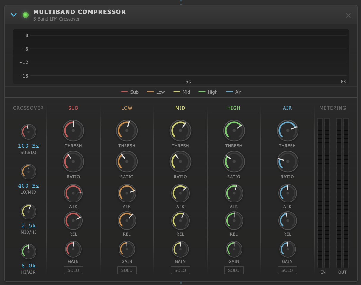
The 5-Band Multiband Compressor with per-band gain reduction meters and crossover frequency controls.
The multiband compressor splits the signal into five frequency bands using Linkwitz-Riley 4th-order (LR4) crossover filters, applies independent compression to each band, and recombines them. This allows precise dynamic control across the spectrum without the pumping artifacts that can occur when a single-band compressor reacts to dominant low-frequency energy.
Crossover Frequencies
Four configurable crossover points define the five bands. Adjacent crossover frequencies are constrained to maintain at least a half-octave separation (1.5x ratio) to prevent filter overlap artifacts.
| Crossover | Range | Default | Bands Separated |
|---|---|---|---|
| 1 | 40 – 300 Hz | 100 Hz | Sub / Low |
| 2 | 150 – 1000 Hz | 400 Hz | Low / Mid |
| 3 | 800 – 6000 Hz | 2500 Hz | Mid / High |
| 4 | 4000 – 16000 Hz | 8000 Hz | High / Air |
Per-Band Controls
Each of the five bands (Sub, Low, Mid, High, Air) has independent dynamics controls:
| Parameter | Range | Description |
|---|---|---|
| Threshold | -40 – 0 dB | Compression onset level for this band. |
| Ratio | 1:1 – 20:1 | Compression ratio for this band. |
| Attack | 0.1 – 100 ms | Compressor attack time. |
| Release | 10 – 1000 ms | Compressor release time. |
| Output Gain | -12 – +12 dB | Makeup gain for this band after compression. |
| Solo | On / Off | Isolate this band for monitoring. Only the soloed band(s) pass to the output. |
All bands use a fixed 3 dB soft knee for smooth compression onset.
Metering
- Per-band gain reduction — individual GR meter for each of the five bands
- GR history — per-band scrolling graphs (20 Hz update rate, 10-second window)
- Band level meters — input and output levels per band
Limiter (Lookahead True-Peak)
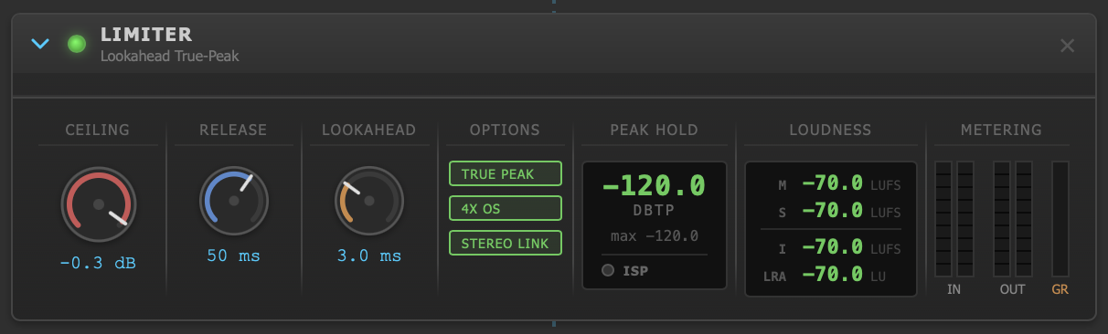
The Limiter with ceiling control, true-peak detection, ISP indicator, and EBU R128 LUFS metering.
The Limiter is the final processor in the chain. It acts as a transparent brickwall limiter with optional lookahead and ITU-R BS.1770-4 true-peak detection. Its primary job is to prevent the output from exceeding a set ceiling while maintaining loudness and minimizing audible artifacts. It also provides comprehensive loudness metering per EBU R128.
Controls
| Parameter | Range | Default | Description |
|---|---|---|---|
| Ceiling | -6.0 – -0.1 dBFS | -0.3 dBFS | Maximum output level. Set to -1.0 dBFS for lossy codecs (AAC/MP3) or -0.3 dBFS for lossless/PCM. |
| Release | 1 – 500 ms | 50 ms | Time for gain to recover after a peak event. |
| Lookahead | 0 – 10 ms | 3 ms | Introduces latency to anticipate peaks, enabling smoother gain reduction. Higher values reduce distortion on transients. |
| True Peak | On / Off | On | Enables ITU-R BS.1770-4 true-peak detection using polyphase FIR interpolation. |
| Oversampling | 1x, 2x, 4x | 4x | Oversampling factor for true-peak detection. 4x uses a 12-tap polyphase filter for inter-sample peak accuracy. |
| Stereo Link | On / Off | On | Links L/R gain reduction to maintain stereo balance. |
Metering and Loudness
The limiter provides the most comprehensive metering in the chain:
Gain Reduction
Current GR in dB, plus a scrolling history graph (20 Hz, 10-second window).
True Peak (dBTP)
Current and maximum true-peak readings with peak hold (10 seconds). Accurate to inter-sample level when oversampling is enabled.
ISP Indicator
Inter-Sample Peak detection. Lights when the reconstructed signal between samples exceeds the ceiling. Includes a cumulative count and 500ms hold.
LUFS Metering
EBU R128 loudness: Momentary (400ms), Short-term (3s), Integrated (program), and Loudness Range (LRA). Uses K-weighted filtering per ITU-R BS.1770-4.
FX Engine
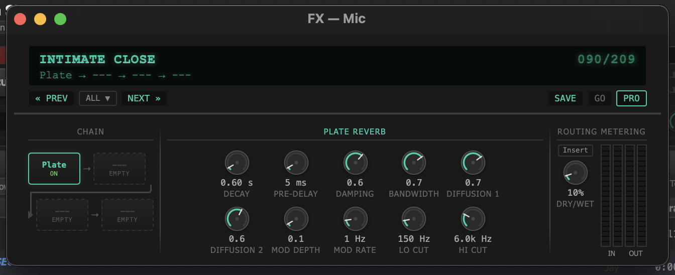
The FX Engine panel with a Plate Reverb algorithm loaded, showing parameter controls and dry/wet mix.
The FX Engine is a multi-slot effects processor that operates independently from the main DSP chain. It can be inserted into the chain as one of the processing stages, or used on individual channels (Deck A, Deck B, Mic, SFX) for per-source processing. Each FX instance provides up to four algorithm slots with a global dry/wet mix control.
Routing Contexts
FX instances can be routed to any of the following contexts:
- Master — inserted into the main DSP chain (affects all program audio)
- Deck A / Deck B — per-deck effects processing
- Mic — voice channel effects (commonly used for reverb and compression on DJ/presenter mic)
- SFX — soundboard effects channel
Available Algorithms
| Algorithm | Category | Description |
|---|---|---|
| Plate Reverb | Reverb | Classic plate-style reverb with size, decay, damping, and pre-delay controls. |
| Mono Delay | Delay | Single-tap delay with feedback, filter, and time controls. |
| Stereo Delay | Delay | Dual-tap delay with independent L/R timing, cross-feedback, and filtering. |
| Chorus | Modulation | LFO-modulated delay for thickening and widening. |
| Tape Saturation | Distortion | Analog tape emulation with drive, warmth, and saturation character. |
| Parametric Filter | Filter | Additional parametric EQ stage for targeted corrections within the FX chain. |
| Pitch Shift | Pitch | Real-time pitch shifting with formant preservation options. |
Preset Browser
The FX Engine includes a preset browser with factory presets organized by category and support for user presets. Presets store the complete state of all four algorithm slots, including which algorithms are loaded, their parameter values, enabled state, and the global dry/wet mix. Apply a preset to instantly recall a saved configuration, or save your own for later use.
Metering
- Input/Output peak levels (L/R) — measured at the boundary of the FX engine
- Per-slot enable/disable — individual bypass for each algorithm slot without unloading
- Dry/Wet mix — blends between the unprocessed and processed signal (0% = fully dry, 100% = fully wet)
Hardware Acceleration
On macOS, JaiCast uses Apple's vDSP (Accelerate framework) for biquad filter processing across the equalizer, compressor sidechain, multiband crossover filters, and limiter K-weighting stages. This offloads per-sample filter computation to hardware-optimized vector routines, reducing CPU load on the audio thread.
All DSP processors operate at the system sample rate (typically 44.1 kHz or 48 kHz) with f64 coefficient precision and f32 sample processing. Filter state is automatically reset when switching between scalar and accelerated code paths to prevent clicks or transients.